Required materials
- 1 Laser board for the Red Pitaya
- 1 Red Pitaya board
- 1 ethernet cable
- 1 power supply
- 2 SMA cables
- 1 SD card with Ubuntu for LBRP image installed
Quickstart
- Mount your Laser board on the Red Pitaya and connect the SMA cables.
- Insert your SD card in the Red Pitaya.
- Connect your Red Pitaya to either a router or a computer with an ethernet cable.
- Plug in the power supply connected to the
PWRslot of the Red Pitaya.
Web interface
Open your internet browser and enter your Red Pitaya IP address in the url bar.
Python API
You can control the laser board programmatically with the Python API. You can find examples of Python scripts on GitHub.
Interface with the Red Pitaya
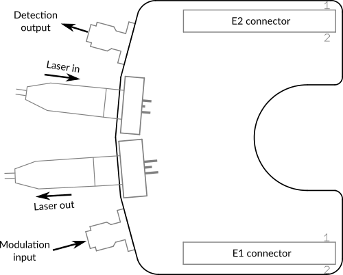
Koheron LBRP2 uses the Red Pitaya extension connectors E1 and E2 for power supply, slow monitoring and control. Modulation input is connected to the 125 MSps DAC via the SMA front connector. Detection output is connected to the 125 MSps ADCs via the SMA front connector.

Digital interface
E1 connector
| Pin | Description | Connected to |
|---|---|---|
| 4 | DIO0_N | EEPROM (DO) |
| 5 | DIO1_P | EEPROM (DI) |
| 6 | DIO1_N | EEPROM (SK) |
| 7 | DIO2_P | EEPROM (CS) |
| 17 | DIO7_P | Laser enable |
| 18 | DIO7_N | Reset overvoltage |
Analog interface
E2 connector
| Pin | Description | Connected to |
|---|---|---|
| 13 | Analog Input 0 | Laser current monitor |
| 15 | Analog Input 2 | Laser power monitor |
| 20 | Analog Output 3 | Laser current bias |
Note: The laser current bias is related to the analog output voltage VAO by ILD (mA) = 47.6 * VAO (V).

